ASCO Manual Transfer Switch: A Comprehensive Guide (Updated 05/04/2026)
ASCO Power Technologies‚ a global leader‚ provides critical power solutions‚ and now integrates Quick Response (QR) Codes across its entire manual transfer switch product line.
This innovative application‚ announced today – May 4th‚ 2026 – enhances support and streamlines access to vital product information for users worldwide.
What is an ASCO Manual Transfer Switch?
An ASCO manual transfer switch is a crucial component in backup power systems‚ designed to safely and reliably transfer electrical load from a primary power source to an alternate source. Unlike automatic transfer switches‚ these require human intervention to switch between power sources – typically utility power and a generator.
These switches are engineered by ASCO Power Technologies‚ a recognized leader in critical power solutions‚ ensuring high standards of performance and durability. They provide a visible disconnect‚ allowing for safe maintenance on either power source. The integration of Quick Response (QR) Codes on all models‚ announced on May 4th‚ 2026‚ further simplifies access to support and documentation.
Essentially‚ an ASCO manual transfer switch acts as a safeguard‚ preventing backfeeding – the dangerous flow of electricity back into the utility grid – during power outages. This makes them indispensable for ensuring power continuity and safety in various applications.
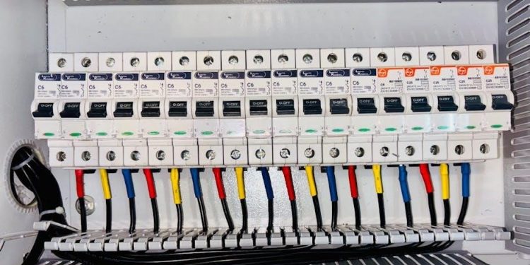
Key Components of an ASCO Manual Transfer Switch
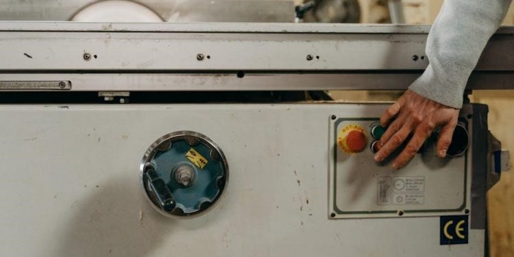
ASCO manual transfer switches comprise several vital components working in unison to ensure safe and reliable power transfer. The core element is the switching mechanism itself – robust contacts designed for frequent operation and high current capacity. A clearly labeled handle or selector switch allows for manual operation between sources.
Enclosures‚ constructed from durable materials‚ protect internal components from environmental factors. Terminal blocks facilitate secure wiring connections‚ while internal barriers provide isolation and safety. Increasingly‚ ASCO Power Technologies is integrating Quick Response (QR) Codes (announced May 4th‚ 2026) directly onto components for instant access to documentation.
Additionally‚ many models include provisions for padlocking in the desired position‚ preventing unauthorized switching. These components‚ combined with ASCO’s engineering expertise‚ deliver a dependable solution for backup power management.
Types of ASCO Manual Transfer Switches
ASCO offers a diverse range of manual transfer switches tailored to various applications and power requirements. These are broadly categorized by amperage and construction. Open transition switches provide a simpler‚ more economical solution‚ briefly interrupting power during transfer. Closed transition models maintain continuous power‚ minimizing disruption – ideal for sensitive equipment.
ASCO also distinguishes switches by mounting style: NEMA 1‚ 3R‚ 4X‚ and 12 enclosures cater to different environmental conditions. Furthermore‚ the May 4th‚ 2026 announcement highlights the integration of Quick Response (QR) Codes across all models‚ simplifying access to specific product details.
Specialty switches are available for unique needs‚ such as those designed for generator testing or specific voltage configurations. Understanding these distinctions is crucial for selecting the optimal switch for a given application.
ASCO 100 Series Manual Transfer Switches
ASCO’s 100 Series represents a foundational line of manual transfer switches‚ designed for light-duty applications. These switches are commonly utilized in residential and light commercial settings‚ offering reliable power transfer for essential circuits. Typically rated up to 100 amps‚ the 100 Series prioritizes simplicity and cost-effectiveness.
Constructed with durable materials‚ they ensure long-term performance in various environments. The series features a compact design‚ facilitating easy installation within existing electrical panels. ASCO’s recent integration of Quick Response (QR) Codes – announced on May 4th‚ 2026 – provides instant access to support resources for these models.
The 100 Series is available in multiple configurations‚ including open and closed transition options‚ catering to diverse power needs and sensitivity requirements.
ASCO 300 Series Manual Transfer Switches
ASCO’s 300 Series manual transfer switches are engineered for medium-duty applications‚ bridging the gap between residential and heavier commercial needs. These switches‚ typically rated up to 200 amps‚ provide a robust solution for critical circuit backup in small businesses‚ and larger residences. They offer enhanced features compared to the 100 Series‚ including increased versatility and durability.
The 300 Series is known for its adaptable design‚ accommodating various generator configurations and load types. ASCO’s implementation of Quick Response (QR) Codes‚ publicized on May 4th‚ 2026‚ simplifies access to technical documentation and support for these models.
Available in both NEMA 1 and NEMA 3R enclosures‚ the 300 Series is suitable for indoor and outdoor installations‚ offering flexibility in placement and protection.
ASCO 700 Series Manual Transfer Switches
ASCO’s 700 Series represents the pinnacle of manual transfer switch technology‚ designed for demanding‚ heavy-duty commercial and industrial applications. These switches‚ capable of handling up to 800 amps‚ ensure uninterrupted power to essential systems during outages. They are built for resilience and longevity‚ offering superior performance in critical environments.
The 700 Series boasts advanced features like enhanced corrosion resistance and customizable configurations to meet specific project requirements. ASCO’s recent integration of Quick Response (QR) Codes – announced on May 4th‚ 2026 – provides immediate access to detailed product information and support resources.
Available in a wide range of voltage and enclosure options‚ the 700 Series delivers unparalleled flexibility and reliability for mission-critical power needs.
Applications of ASCO Manual Transfer Switches
ASCO Manual Transfer Switches serve a diverse range of applications‚ ensuring power continuity across various sectors. From safeguarding essential services in residential settings to maintaining operations in commercial and industrial facilities‚ ASCO provides tailored solutions.
These switches are crucial for powering emergency systems like backup generators‚ life safety equipment‚ and critical loads during utility outages. The versatility of ASCO’s product line‚ including the innovative integration of Quick Response (QR) Codes – announced on May 4th‚ 2026 – allows for seamless implementation in diverse environments.
Whether it’s a small business‚ a large hospital‚ or a manufacturing plant‚ ASCO transfer switches deliver reliable power transfer‚ minimizing downtime and protecting valuable assets.
Residential Use Cases
ASCO Manual Transfer Switches are increasingly vital for homeowners seeking reliable backup power solutions. They enable safe connection of portable generators to power essential circuits during utility outages‚ safeguarding critical appliances like refrigerators‚ heating systems‚ and medical equipment.
Unlike potentially dangerous backfeeding through standard outlets‚ ASCO switches provide a secure‚ code-compliant method for distributing generator power throughout the home. The recent integration of Quick Response (QR) Codes – highlighted on May 4th‚ 2026 – simplifies troubleshooting and access to support resources for homeowners.
These switches offer peace of mind‚ ensuring comfort and safety during emergencies‚ and protecting valuable household contents from power-related damage. They represent a smart investment for homeowners in areas prone to frequent power disruptions.
Commercial Use Cases
ASCO Manual Transfer Switches are crucial for businesses needing uninterrupted power to maintain operations during outages. They protect sensitive equipment‚ prevent data loss‚ and ensure continued service for customers‚ minimizing financial repercussions from downtime. Applications span retail stores‚ offices‚ and small manufacturing facilities.
These switches allow businesses to seamlessly switch to generator power‚ maintaining critical functions like security systems‚ lighting‚ and essential machinery. The recent implementation of Quick Response (QR) Codes – announced on May 4th‚ 2026 – provides rapid access to technical support and documentation‚ reducing repair times.
Investing in an ASCO switch demonstrates a commitment to business continuity and customer satisfaction‚ safeguarding revenue and reputation during unforeseen power interruptions.
Industrial Use Cases
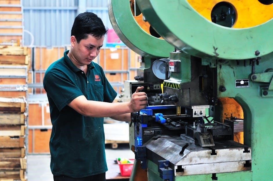
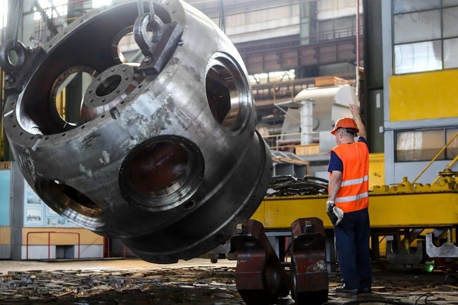
ASCO Manual Transfer Switches are vital in industrial settings where even brief power interruptions can cause significant production losses and equipment damage. They safeguard critical processes in manufacturing plants‚ water treatment facilities‚ and data centers‚ ensuring operational continuity.
These switches facilitate a swift transition to emergency power sources‚ protecting sensitive machinery‚ control systems‚ and safety equipment. The integration of Quick Response (QR) Codes – a recent development highlighted on May 4th‚ 2026 – offers immediate access to troubleshooting guides and support resources‚ minimizing downtime.
Reliable power transfer is paramount for maintaining product quality‚ meeting production schedules‚ and upholding safety standards within demanding industrial environments. ASCO solutions deliver the robustness and dependability required for these critical applications.
Installation Considerations for ASCO Manual Transfer Switches
Proper installation is crucial for optimal performance and safety; always adhere to national and local electrical codes‚ and utilize qualified personnel for setup.
Safety Precautions During Installation
Prioritizing safety during the installation of an ASCO manual transfer switch is paramount. Always disconnect all power sources – both normal and emergency – before commencing any work. Verify the absence of voltage using appropriate testing equipment. Qualified electricians should perform all wiring‚ adhering strictly to the National Electrical Code (NEC) and local regulations.
Wear appropriate personal protective equipment (PPE)‚ including safety glasses‚ insulated gloves‚ and arc-rated clothing. Ensure the work area is well-lit and free of obstructions; Never work alone; a second qualified person should be present for assistance and emergency support. Proper grounding is essential to prevent electrical shock and equipment damage. Double-check all connections before energizing the system. Follow ASCO’s installation manuals meticulously‚ and heed all warning labels. Ignoring these precautions can lead to severe injury or death.
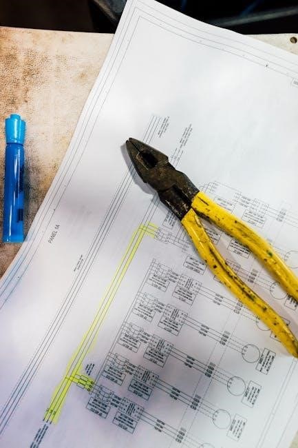
Wiring Diagrams and Best Practices
Accurate wiring is crucial for the reliable operation of an ASCO manual transfer switch. Always refer to the specific wiring diagram provided with your model‚ as configurations vary. Utilize appropriately sized conductors‚ ensuring they meet or exceed the switch’s ampacity rating. Maintain neat and organized wiring‚ using conduit and cable ties for a professional and safe installation.
Properly torque all connections to the manufacturer’s specifications. Avoid sharp bends in conductors‚ which can damage insulation. Clearly label all wiring for easy identification during maintenance and troubleshooting. Implement a dedicated grounding system‚ connecting the switch enclosure to a suitable earth ground. Consider using color-coded wiring to differentiate between phases and neutral. Regularly inspect wiring for signs of damage or corrosion‚ addressing any issues promptly. Following these best practices ensures a secure and efficient power transfer system.
Code Compliance and Regulations
ASCO manual transfer switches must adhere to stringent electrical codes and regulations for safe and legal operation. Compliance with the National Electrical Code (NEC) is paramount‚ particularly sections pertaining to emergency and standby systems. Local authorities may have additional requirements‚ so consult with your local inspection department before installation.
Ensure the switch is appropriately listed and labeled by a recognized testing laboratory‚ such as UL. Proper grounding and bonding are critical for safety and code adherence. Qualified electricians must perform all wiring and installation work. Documentation‚ including wiring diagrams and installation instructions‚ should be readily available for inspection. Regular inspections and testing are necessary to maintain compliance. Failure to comply with applicable codes can result in fines‚ safety hazards‚ and voided warranties.

Operation and Maintenance of ASCO Manual Transfer Switches
Regular inspection and testing are crucial for optimal performance and longevity of ASCO switches‚ alongside understanding proper switching procedures for seamless transitions.
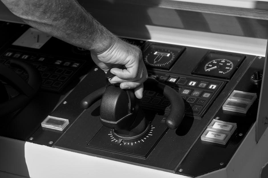
Switching Procedures: Normal to Emergency & Vice Versa
Proper switching procedures are paramount when operating an ASCO manual transfer switch‚ ensuring a safe and reliable power transition. Before initiating any switchover‚ disconnect the load if possible‚ minimizing stress on the system. To switch from normal to emergency power‚ firmly rotate the handle to the ‘Emergency’ position; a distinct mechanical action confirms engagement.
Verify the emergency source is energized and stable before connecting it to the load. Conversely‚ returning to normal power requires rotating the handle back to ‘Normal‚’ again confirming mechanical engagement. Always ensure the normal source is stable before reconnecting.
Crucially‚ avoid ‘floating’ the switch in the center position‚ as this disconnects the load from both sources‚ potentially causing equipment shutdown or damage. ASCO’s design incorporates clear labeling and robust mechanics to guide users‚ but thorough training is recommended for all personnel responsible for operation. Following these steps guarantees a smooth and secure power transfer.
Routine Inspection and Testing
Regular inspection and testing of your ASCO manual transfer switch are vital for maintaining optimal performance and ensuring reliability during critical power outages. A visual inspection should be conducted monthly‚ checking for loose connections‚ corrosion‚ or any physical damage to the switch and its enclosure.
Quarterly testing involves manually switching between normal and emergency power sources‚ verifying proper operation and voltage levels. Document these tests meticulously‚ noting any anomalies. ASCO’s Quick Response (QR) Codes provide access to detailed testing procedures and support resources.
Annual preventative maintenance‚ performed by a qualified electrician‚ should include a thorough cleaning‚ lubrication of moving parts‚ and torque verification of all connections. This proactive approach extends the switch’s lifespan and guarantees it will function flawlessly when needed most‚ safeguarding your operations.
Troubleshooting Common Issues
Addressing issues promptly is crucial for maintaining a functional ASCO manual transfer switch. A frequent problem is failure to transfer‚ often caused by tripped breakers or loose wiring – verify power supply to both sources. Voltage imbalances can indicate wiring faults or generator problems; consult a qualified electrician for diagnosis.
Overheating may signal overloaded circuits or insufficient ventilation. Ensure the switch isn’t exceeding its rated capacity. Difficulty in switching could stem from mechanical binding; lubrication might resolve this. Utilize ASCO’s QR Codes for instant access to troubleshooting guides and expert support.
Remember‚ safety is paramount. Always disconnect power before attempting any repairs. If issues persist‚ contact a certified technician to prevent further damage or safety hazards.
ASCO’s Quick Response (QR) Code Technology for Support
ASCO Power Technologies has revolutionized support for its manual transfer switches with the integration of Quick Response (QR) Codes on all models. These codes‚ readily accessible on the switch itself‚ provide instant access to a wealth of resources via smartphone or tablet.

Scanning a QR code directs users to detailed product information‚ including specifications‚ wiring diagrams‚ and troubleshooting guides. Furthermore‚ it unlocks direct access to ASCO’s support network‚ facilitating quick connections with technical experts. This technology minimizes downtime and empowers users with self-service capabilities.
This innovative approach streamlines the support process‚ offering a convenient and efficient way to resolve issues and ensure optimal performance of your ASCO manual transfer switch. It’s a commitment to customer satisfaction and proactive problem-solving.

Benefits of Choosing ASCO Manual Transfer Switches
ASCO delivers unparalleled reliability and durability in its transfer switches‚ enhanced by innovative features like QR code support for swift troubleshooting and assistance.
Reliability and Durability
ASCO Manual Transfer Switches are engineered for exceptional performance and longevity‚ crucial for maintaining power continuity during outages. These switches undergo rigorous testing to ensure they withstand demanding conditions and deliver consistent‚ dependable operation.
The robust construction‚ utilizing high-quality materials‚ minimizes wear and tear‚ extending the switch’s service life. ASCO’s commitment to quality control throughout the manufacturing process guarantees a product built to last. This dedication translates to reduced downtime‚ lower maintenance costs‚ and increased peace of mind for end-users.
Furthermore‚ the integration of Quick Response (QR) Codes directly onto the switches facilitates rapid access to support resources‚ aiding in swift diagnosis and resolution of any potential issues‚ ultimately bolstering the overall reliability of the system; Choosing ASCO means investing in a durable solution designed for years of trouble-free service.
Cost-Effectiveness
ASCO Manual Transfer Switches represent a smart investment‚ offering a balance between upfront cost and long-term value. While initial investment is a factor‚ the reduced downtime and minimized maintenance requirements contribute significantly to overall cost savings.
The durable construction and reliable performance of ASCO switches translate to fewer repairs and replacements over their lifespan. Moreover‚ the newly implemented Quick Response (QR) Code technology streamlines troubleshooting‚ reducing service call expenses and accelerating issue resolution.
By preventing costly disruptions and ensuring business continuity‚ ASCO switches protect against revenue loss and maintain operational efficiency. This proactive approach to power management ultimately delivers a strong return on investment‚ making ASCO a cost-effective solution for critical power needs.